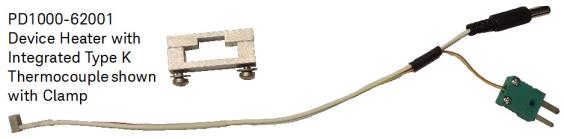
Using the (Optional) Device (DUT) Heaters
When making a Double-Pulse Test measurement with the Device Heater(s) activated and valid temperature(s) specified, the Control Software automatically initiates the measurement when the heater reaches the specified temperature. However, there are several details to consider:
-
DUT temperature affects the following: Ton transition time, Ton and Toff delay time, Turn on dv/dt, Ton and Toff di/dt,
- Are the heater and thermocouple connect to the DUT?
- Are the heater and thermocouple connect to the Test Fixture?
- Is the heater activated in the PD1000A DPT Control Software?
- You may want the heater to settle at the specified temperature before initiating the DPT measurement. Don’t forget that the heater needs to heat a large thermal mass including the DUT itself and the aluminum clamp.
- After the heater reaches the specified temperature, it may take a few seconds for the internal die of the device itself to reach that temperature.
-
If the Low-Side heater fails to achieve the specified temperature within the specified time, the DPT test aborts.
This section explains how the device heating system and various temperature settings in the Control Software work together.
Using the Talenia Electronics High-Side Device Heater
Requires Software version 2020.820 or later and Test Fixture Firmware A.01.03 or later.
Maximum temperature for D2PAK or GaN devices is limited to structure and device heat dissipation. It is not possible to determine the actual temperature of the die. Do not exceed 150 °C.

Hot Surface; DO NOT Touch! When the PD1500Adevice heater is used to heat the DUT, it becomes very hot. Do not touch the heater or the clamp. Do not allow flammable material (such as paper) to come into contact with the heater while it is hot.
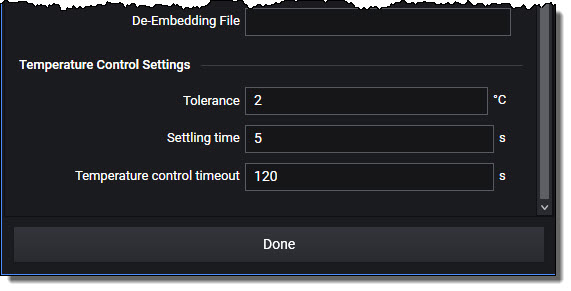
Configure Temperature Control Settings
In the Settings > Hardware Configuration > Fixture menu, set the following:
-
Tolerance: Specify a range (±) around the specified temperature for triggering the DPT measurement. For example, if you specify making a DPT measurement at 100 °C and a 1 °C Tolerance, then the measurement is triggered somewhere between 99 °C and 101 °C.
-
Settling Time: Specify a time period (in seconds) to wait after the heater reaches the specified temperature (within the specified Tolerance) before triggering the DPT measurement.
-
Temperature Control Timeout: Specify the maximum time period (in seconds) to wait for the device to reach the specified temperature before triggering the measurement. If the device does not reach the specified temperature within this time period, the Double-Pulse Test aborts.
For example, to go from ambient temperature (~25 °C) to 100 °C with a 2 °C Tolerance may take up to 60 seconds. To go from Ambient temperature to 100 °C with a 1 °C Tolerance may take up to 90 seconds.
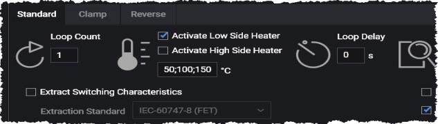
Activate the Low-Side Heater and Setting Test Temperatures
-
Activate Low-Side Heater: (checkbox) Turns the heater circuit on or off for the Low-Side device.
-
Activate High-Side Heater: This box is grayed-out unless Activate Low-Side Heater is checked. Before you check the Activate High-Side Heater box, make certain that a heater/thermocouple assembly is connected to both High-Side and Low-Side devices. See “Using the Talenia Electronics High-Side Device Heater” for detailed information on installing and using the optional High-Side heater.
-
Temperatures: Enter a single value or a semicolon (;) delimited list of temperatures to heat the device to when running the DPT tests. This box is grayed-out unless Activate Low-Side Heater is checked.
The temperature display shows the temperature at the time of the measurement. It is not updated during the heating process or while the device is cooling. For the current temperature, click the Refresh button. If you do not have the High-Side heater installed, or for any temperatures the system cannot read, the display shows “NaN” (Not a Number).

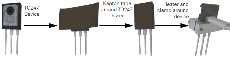
Adding Kapton (polyimide) Tape to TO-247-3 and -4 Devices
Keysight recommends wrapping one layer of Kapton (polyimide) tape (for example, Keysight part number 0460-3128, 0.75 inch wide, 2.7 mil thick) around the TO-247 device before attaching the heater bracket.
-
Wrap the TO247 Device in one layer of Kapton tape.
-
Use a Torx T8 screw driver on clamp screws
-
Tighten only enough to hold the DUT and heater assembly together. Do not over tighten.
Device Heater Theory of Operation
If the device heater operated in a pure vacuum, the heating curve would be a simple straight line -- you apply a certain amount of energy to the heater and it heats to the desired temperature. But in a real-world test system, there are more issues involved. The heater heats not only itself, but also the DUT, the aluminum clamp, plus a small amount of heat is lost to the air.
Therefore, a control circuit applies energy to the heater, monitors its temperature (via a K-type thermocouple) and tries to regulate at the desired temperature. In the PD1500A, the temperature is sampled approximately 10 times per second. The heater itself has a theoretical capacity to heat itself up to 175 °C per second. In 1/10 of a second then, the heater can raise its temperature approximately 15 °C. So, if you set a small temperature increase, let’s say 10 °C, then in 1/10 of a second, the heater can overshoot your desired temperature by 5 °C. Again, it is slightly less than that because heat is transferred to the device, the clamp, surrounding air, etc.
The heater has no capacity to actively “cool” a device; it can only provide heat. Therefore, to lower the temperature, the system must remove energy from the heater and allow the heat to dissipate. This may take longer than the 1/10 of a second until the next temperature sample.
If you set a large temperature change, for example, from 22 °C to 100 °C, then it may take several seconds to arrive at the desired temperature. Again, there is the possibility of slight temperature overshoot.
Figure below shows the fields in the Hardware Configuration used to set the Temperature Tolerance and Settling Time.
In the following figure , Desired Temperature is set in the main screen of the DPT control software. Several temperatures may be set with a semicolon list (for example, 25;50;100;150).

Heater Stability
The following table lists typical (not guaranteed) temperature deviation after the specified time. Settings > Hardware Configuration > Tolerance set to 2 °C.
| Specified Temperature | Temp. after 30 seconds | Temp after 1 min. | Temp after 2 min. | Temp after 5 min. | Delta after 5 minutes |
|---|---|---|---|---|---|
| TO-247 Devices | |||||
| 30 °C | 29.67 °C | 29.71 °C | 29.73 °C | 29.73 °C | -0.27 °C |
| 50 °C | 49.47 °C | 49.50 °C | 49.51 °C | 49.51 °C | -0.49 °C |
| 100 °C | 99.06 °C | 99.10 °C | 99.12 °C | 99.15 °C | -0.96 °C |
| 150 °C | 148.72 °C | 148.76 °C | 145.75 °C | 148.79 ° | -1.21 °C |
| D2PAK-7 Devices | |||||
| 30 °C | 31.30 °C | 29.80 °C | 29.81 °C | 29.81 °C | -0.19 °C |
| 50 °C | 49.52 °C | 49.56 °C | 49.28 °C | 49.58 °C | -0.42 °C |
| 100 °C | 99.23 °C | 99.22 °C | 99.23 °C | 99.23 °C | -0.77 °C |
| 150 °C | 148.93 °C | 148.91 °C | 148.91 °C | 148.94 °C | -1.06 °C |
Using the Device Heater
There are two parts to configuring the PD1500A Device Heater:
- Configuring the Temperature Control Settings
- Activating the Heater and specifying Temperatures to test the DUT
Configuring Temperature Control Settings in the Hardware Configuration Setup
- Tolerance:Specify a range (±) around the specified temperature for triggering the DPT measurement. For example, if you specify making a DPT measurement at 100 °C and a 1 °C Tolerance, then the measurement is triggered somewhere between 99 °C and 101 °C.
- Settling Time: Specify a time period (in seconds) to wait after the heater reaches the specified temperature (within the specified Tolerance) before triggering the DPT measurement.
- Temperature Control Timeout: Specify the maximum time period (in seconds) to wait for the device to reach the specified temperature before triggering the measurement. If the device does not reach the specified temperature within this time period, the Double-Pulse Test aborts.
For example, to go from ambient temperature (~25 °C) to 100 °C with a 2 °C Tolerance may take up to 60 seconds.To go from Ambient to 100 °C with a 1 °C Tolerance may take up to 90 seconds.
The table below lists several examples and expected results when using the PD1500A Heater and Thermocouple. It assumes the following test conditions:
- Gate High Voltage: 18 V
- Gate Low Voltage: -2 V
- VDS: 300 V
- ID: 10 A
- Tolerance: 20%
- Temperature Range: 1 °C
- Temperature Timeout: 30 seconds.
Measurements Using Heater and Thermocouple
| Temperature(s) Specified (in PD1000A Software) | Heater Activated (in PD1000A Software) | Thermocouple Connected to Test Fixture | Heater Connected to Test Fixture | Expected Result |
|---|---|---|---|---|
| 50 °C | YES | YES | YES | Test runs normally at a temperature between 49 °C and 51 °C. Temperature is recorded. |
| 50;60 °C | YES | YES | YES | Both tests run normally at temperature: First test between 49 °C and 51 °C. Second test between 59 °C and 61 °C. Temperatures are recorded. |
| 50 °C | NO | YES | YES | Test runs normally but with no heating. Device temperature is recorded. |
| 50 °C | NO | YES | NO | Test runs normally but with no heating. Device temperature is recorded. |
| 50 °C | NO | NO | NO | Test runs normally but with no heating. No temperature (NaN) is recorded. |
| 50 °C | YES | NO | NO | Test aborts with the error message, “Failed to read temperature. Is a thermocouple connected?” |
| 50 °C | YES | YES | NO | Test aborts with the error message, “The heater did not respond. Is the heater connected?” |
| 50 °C | YES | NO | YES | Test aborts with the error message, “Failed to read temperature. Is a thermocouple connected?” |